push time:2023-06-26 Popularity: source:1
Angle displacement sensor application for obstacle handling: Using an angle sensor to control your wheels can easily detect obstacles. The principle is very simple. If the motor angle sensor structure operates and the gear does not rotate, it indicates that your machine has been blocked by obstacles. This technology is very simple to use and very effective; The only requirement is that the moving wheels cannot slip on the floor (or slip too many times), otherwise you will not be able to detect obstacles. An idle gear connected to the motor can avoid this problem, as the wheel is not driven by the motor but is driven by the movement of the device. If the idler wheel stops during the rotation of the drive wheel, it indicates that you have encountered an obstacle.
An angle displacement sensor is an electronic component that uses angle changes to locate the position of an object. Suitable for servo systems of automobiles, engineering machinery, space devices, missiles, aircraft radar antennas, as well as injection molding machines, woodworking machinery, printing machines, electronic rulers, robots, engineering monitoring, computer-controlled motion equipment, and other occasions that require precise displacement measurement. This article introduces the principle and application examples of angle displacement sensors.
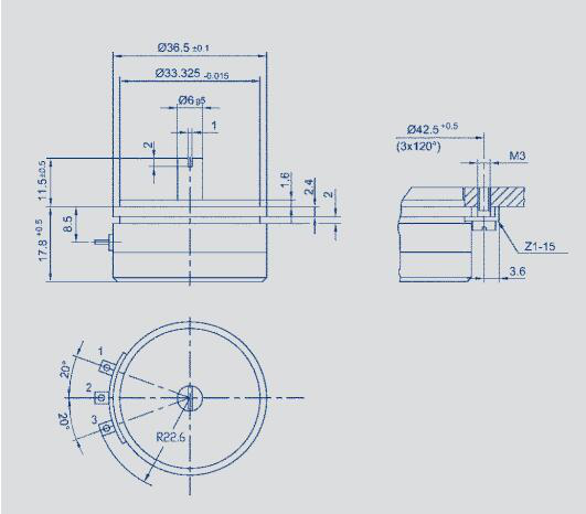
Principle of angle displacement sensor
An angle sensor is used to detect angles. It has a hole in its body that can fit the axis of LEGO. When connected to the RCX, the angle sensor counts every 1/16 turn of the shaft. When rotating in one direction, the count increases, and when the direction of rotation changes, the count decreases. The counting is related to the initial position of the angle sensor. When initializing the angle sensor, its count value is set to 0. If necessary, you can reset it through programming.
Example of angle displacement sensor
If the angle sensor is connected to any transmission shaft between the motor and the wheel, the correct transmission ratio must be included in the read data. Give an example of calculation. On your robot, the motor is connected to the main wheel with a 3:1 transmission ratio. The angle sensor is directly connected to the motor. So its transmission ratio to the driving wheel is also 3:1. That is to say, the angle sensor rotates three times and actively rotates once. The angle sensor measures 16 units per revolution, so 16 * 3=48 increments are equivalent to one revolution of the driving wheel. Now, we need to know the circumference of the gear to calculate the travel distance. Fortunately, each LEGO gear tire is labeled with its own diameter. We chose the wheel with the largest volume and a shaft, with a diameter of 81.6CM (Lego uses metric units), so its circumference is 81.6& Times& Amp; Pi= 81.6& Times; 3.14& Asymp; 256.22CM. Now all known quantities are available: the running distance of the gear is recorded by dividing the angle by 48 and then multiplying by 256. Let's summarize. R is the resolution of the angle sensor (calculated per revolution), and G is the transmission ratio between the angle sensor and the gear. We define I as the increment of the wheel rotation angle sensor. Namely:
I=G×R
In the example, G is 3, and for the LEGO angle sensor, R has always been 16. Therefore, we can obtain:
I=3×16=48
Every time the gear rotates, the distance it passes through is exactly its circumference C. Applying this equation and using its diameter, you can come to this conclusion.
C=D×π
In our example:
C=81.6×3.14=256.22
The final step is to convert the data recorded by the sensor - S into the distance of wheel movement - T, using the following equation:
T=S×C/I
If the value read by the photoelectric sensor is 296, you can calculate the corresponding distance:
T=296& Times; 256.22/48=1580 The unit of distance (T) is the same as the unit of wheel diameter
Practical Application of Angular Displacement Sensors
applyAngle sensors can indirectly detect obstacles by controlling your wheels. The principle is very simple: if the motor angle sensor structure operates and the gear does not rotate, it indicates that your machine has been blocked by obstacles. This technology is very simple to use and very effective; The only requirement is that the moving wheels cannot slip on the floor (or slip too many times), otherwise you will not be able to detect obstacles. If it is an idle gear connected to the motor, this problem can be avoided. The wheel is not driven by the motor, but is driven by the movement of the device. During the rotation of the driving wheel, if the idle gear stops, it indicates that you have encountered an obstacle.
Angle sensors are very useful in many situations: controlling the position of arms, head, and other movable parts. It should be noted that when the running speed is too slow or too fast, RCX will be affected in terms of precise detection and counting. In fact, the problem is not with RCX, but with its operating system. If the speed exceeds its specified range, RCX will lose some data. Steve Baker has demonstrated through experiments that a speed range of 50 to 300 revolutions per minute is a suitable range, and there will be no problem of data loss within this range. However, within the range of less than 12rpm or more than 1400rpm, there may be some data loss issues. In the range of 12rpm to 50rpm or 300rpm to 1400rpm, RCX may occasionally experience data loss issues.
Angle displacement sensors can be divided into static and dynamic, and many precision instruments now require angle displacement sensors. With the development of measurement and control technology, angle displacement sensors will inevitably develop towards high-precision, miniaturization, and intelligence.

Sales contact information:
Miss Chen:
sales@zhongxintmt.com
Mr. Huang:
huanghao@zhongxintmt.com


 Sales Engineer - Miss Chen