push time:2023-06-26 Popularity: source:1
2、 The Principles and Differences of Three and Four Wire Transmitters
Different wire systems refer to various outputs that are analog DC current signalsWeight transmitterThe difference in its working principle and structure, rather than just referring to the wiring form of the transmitter.
The term 'several wire system' came into existence after the birth of two wire transmitters. This is the result of the widespread application of electronic amplifiers in instruments. The essence of amplification is an energy conversion process, which cannot be separated from power supply. Therefore, the first to appear were four wire transmitters; Two wires are responsible for the power supply, and the other two wires are responsible for outputting signals that are converted and amplified (such as voltage, current, etc.). The emergence of the ddz - ii type electric unit combination instrument, a four wire transmitter with a power supply of 220v. ac and an output signal of 0-10MA. DC, has been widely used, and its presence can still be seen in some factories.
In the 1970s, China began producing DDZ III electric unit combination instruments and adopted the International Electrotechnical Commission (IEC) standard for analog signals used in process control systems. The instrument transmission signal adopts 4-20MA.DC, and the contact signal adopts 1-5V.DC, which is a signal system that uses current transmission and voltage reception. By using 4-20MA.DC signals, on-site instruments can achieve a two wire system. However, due to limitations, the two wire system was only used on pressure and differential pressure transmitters at that time, while temperature transmitters still used the four wire system. The product range of two wire transmitters in China has greatly expanded and their application fields are also increasing. At the same time, the majority of transmitters imported from abroad are also two wire systems.
The essence of the two wire system is that the power supply and load are connected in series, with a common point. However, the signal connection and power supply between the on-site transmitter and the control room instrument only use two wires, which are both power and signal wires. Due to the signal starting point current of 4MA.DC, the two wire transmitter provides static working current for the transmitter, and the instrument electrical zero point is 4MA.DC, which does not coincide with the mechanical zero point; Ldquo; Live Zero Point; Rdquo; It is conducive to identifying faults such as power outage and wire breakage. Moreover, the two wire system also facilitates the use of safety barriers, which is conducive to safety and explosion protection.
As shown in Figure 1, the two-wire power supply is 24v.dc, the output signal is 4-20MA.DC, and the load resistance is 250 amp; Omega;, The negative line potential of the 24V power supply is the lowest, which is the signal common line. For smart transmitters, the fsk keying signal of the hart protocol can also be loaded onto the 4-20MA.DC signal.
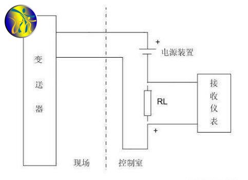
Figure 1
As shown in Figure 2, the three wire system means using one wire for the positive end of the power supply, one wire for the positive end of the signal output, and one wire for the negative end of the power supply and the negative end of the signal. Its power supply is mostly 24v.dc, with an output signal of 4-20MA.DC and a load resistance of 250 amp; Omega; Or 0-10MA.DC, with a load resistance of 0-1.5k; Omega;; Some also have ma and mv signals, but the load resistance or input resistance may have different values due to different output circuit forms.
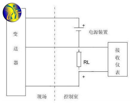
Figure 2
As shown in Figure 3, due to the popularity and application of the 4-20MA.DC (1-5v. dc) signal system, in order to facilitate connection in control system applications, unified signal system, complex conversion circuits, and high power consumption are required. Therefore, an external power source can only be used to produce a four wire transmitter with an output of 4-20MA.DC. Most of its power supply is 220v. ac, and there are also those with a power supply of 24v. dc. The output signal has 4-20MA.DC and the load resistance is 250 amp; Omega;, Or 0-10MA.DC, with a load resistance of 0-1.5k; Omega;; Some also have ma and mv signals, but the load resistance or input resistance may have different values due to different output circuit forms.
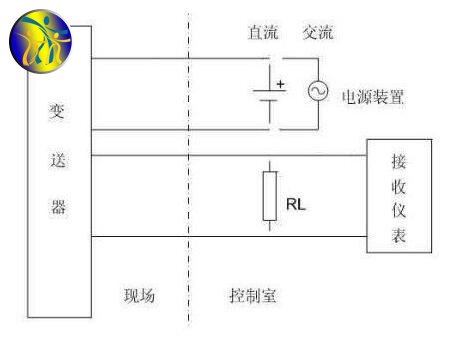
Figure 3

Sales contact information:
Miss Chen:
sales@zhongxintmt.com
Mr. Huang:
huanghao@zhongxintmt.com


 Sales Engineer - Miss Chen