push time:2023-06-26 Popularity: source:1
We assume that the sensitivity of the weighing sensors is S1 and S2, the resistance of the bridge arm is R1 and R2, the supply voltage of the bridge is U1 and U2, and the full scale is F. The condition for these two sensors to operate in parallel is S1R1=S2R2. Obviously, the parameter requirements of the sensors themselves are relatively high when operating in parallel.
Similarly, when n load cells operate in parallel, it can be obtained that S1/R1=S2/R2=& Hellip= Sn/Rn.
The characteristics of two sensors working in parallel are as follows:
1) Assuming that for a certain load W, we measure it with a sensor with full scale F, sensitivity S, and bridge voltage U, and output U1, then U1=WSU/F. If two sensors operate in parallel and measure the same load W above, ideally, a sensor with a full range of (1/2) F can be selected. Assuming their sensitivity is also S and the bridge voltage is also U, the total output Un is: Un=U1
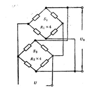
Figure 1 Parallel operation mode of weighing sensors
2) Assuming that the bridge arm resistance of both sensors is R and the output impedance after parallel connection is Rn, it is obvious that Rn=R/2.
Similarly, it can be proven that when n sensors operate in parallel, there is: Un=" U1" Rn=R/n
Un=" in the above equation; U1", Rn is the output signal and output impedance of n sensors working in parallel. These two formulas indicate that no matter how many sensors work in parallel, they will not obtain a larger output than an equivalent sensor, but the output impedance after parallel operation decreases to 1/n of one sensor.
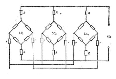
Figure 2- Full parallel operation mode with isolation resistor connected
Under the condition that the weighing display controller has high sensitivity or resolution, it is better to use the parallel method because it only requires one power supply bridge, making the system simple and economical. But it requires that the average deviation of the output impedance of each sensor be small, and the tolerance of the sensor coefficient should not be too large. Otherwise, when several sensors are subjected to uneven forces, the average output voltage will produce an error. When working in parallel in foreign countries, most of them connect two isolation resistors between the two output terminals of each transducer and the matched weighing display. Due to the fact that the internal resistance of the sensor is a function of the output signal, serializing isolation resistors can reduce the impact of resistance changes on the output. The total resistance value of the two isolation resistors of each sensor should be equal, and these two resistors themselves should also be equal, with a small tolerance. This can reduce the impact of unequal sensor output impedance or inconsistent sensor coefficients on the total output of the sensor. The connection method is shown in Figure 2.
Experiments have shown that when sensors operating in parallel are subjected to uneven loads, the average error of the sensors is less than 0.05%. In Figure 3, R is the isolation resistance, usually around 10kO, with a tolerance of 0.01%.

Sales contact information:
Miss Chen:
sales@zhongxintmt.com
Mr. Huang:
huanghao@zhongxintmt.com


 Sales Engineer - Miss Chen